SOLIDWORKS Tutorials: Advancement in Hole Wizard Tool
August 7, 2024 2024-11-11 13:26SOLIDWORKS Tutorials: Advancement in Hole Wizard Tool
SOLIDWORKS Tutorials: Advancement in Hole Wizard Tool
In this SOLIDWORKS tutorial, we explore the latest enhancements in the Hole Wizard’s Positions tab, a key feature for streamlining hole creation in CAD designs. This powerful tool now offers increased flexibility by allowing you to select from existing 2D sketches for precise hole placement, choose from various positioning options, and manage hole position sketches with greater control. By leveraging these advancements, you can significantly improve the efficiency of your CAD design workflow.
Steps to leverage the hole creation process in SOLIDWORKS Hole Wizard Tool:
Step 1:
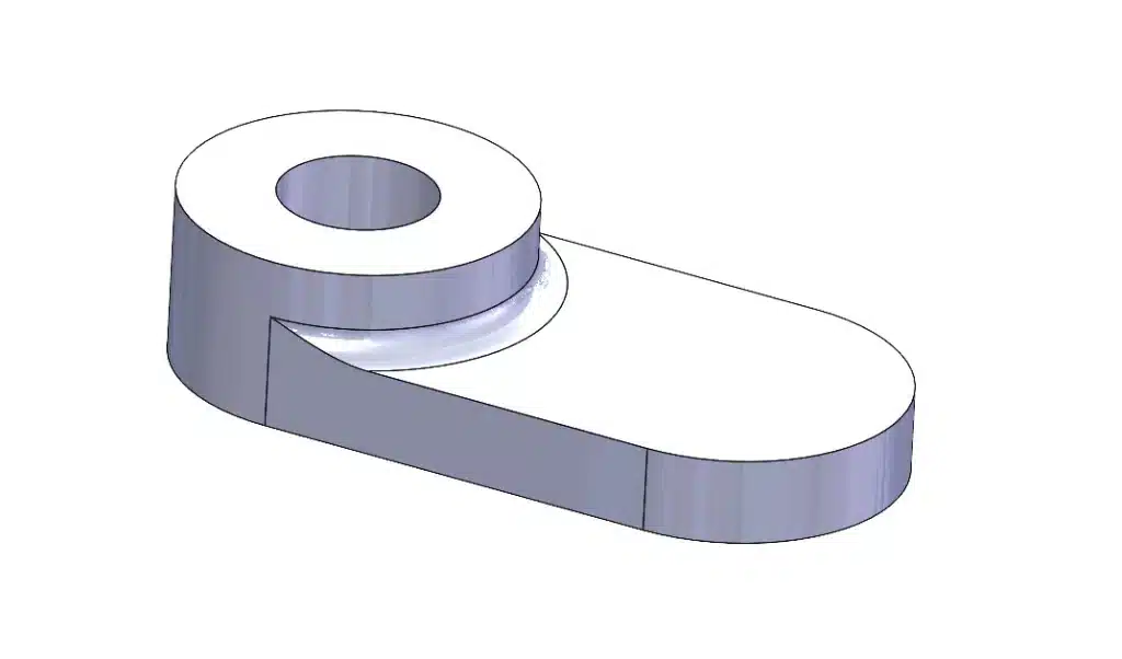
Begin by launching SOLIDWORKS User Interface and opening the project Round_About_Foot.SLDPRT.

Step 2:
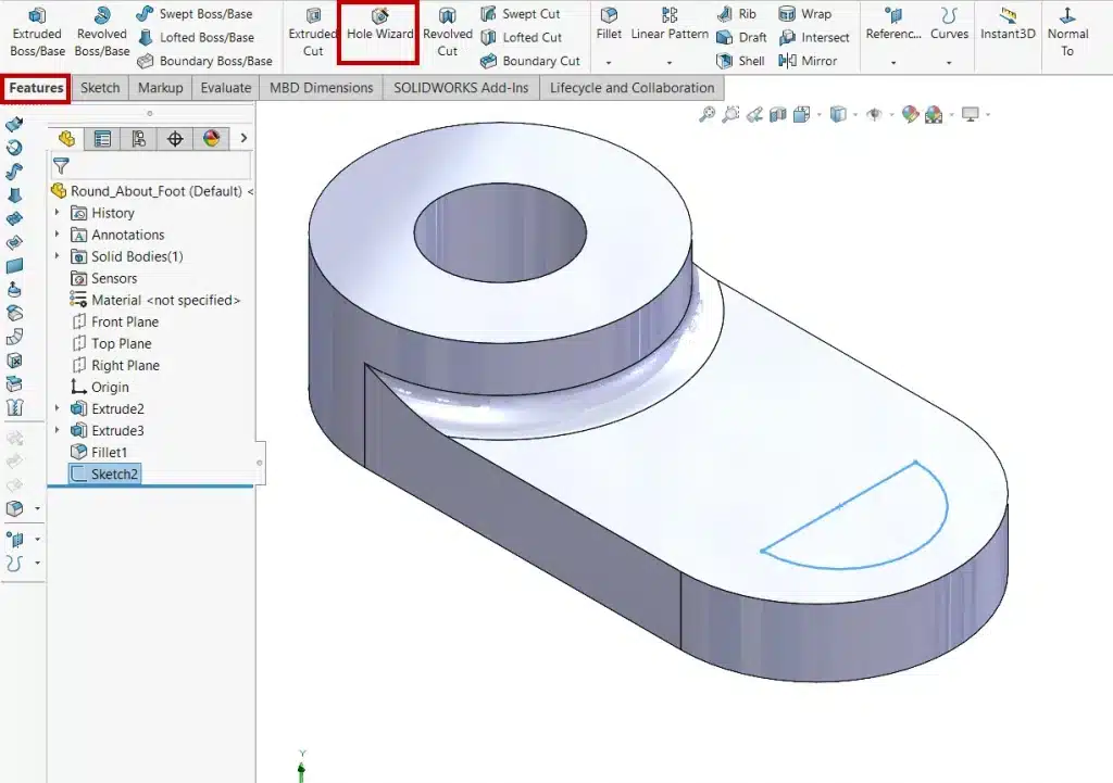
Before accessing the Hole Wizard Tool make sure that 2D sketch is drawn on the part where we need to create holes.

Step 3:
Access the Hole Wizard Tool under Features tab.

Step 4:
In the Hole Wizard dialog box, select ‘Counterbore’ as hole type.

Step 5:
Specify the parameters that include the hole’s diameter, depth, and other relevant characteristics.

Step 6:
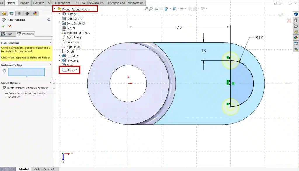
Under the Positions tab in the Hole Wizard, specify the hole position. Use an Existing 2D sketch or create a new one.
Within the Sketch Options section, you can make specific choices:
1) Create instances on sketch geometry (Enabled by default): This option places holes at all endpoints, vertices, and points of our selected sketch geometry.
2) Create instances on construction geometry: Choose this if we want the holes to follow a different construction geometry.

Step 7:
Expand the design Tree and select the sketch which we sketched earlier.

Step 8:
Holes will automatically create at the instances on sketch geometry. With our sketch or construction geometry in place, we can specify the exact locations for the holes. Left Click on endpoints, vertices, or points on the geometry to indicate where the holes should go. This is much like marking the exact spots where we want to drill holes in a physical material.

Step 9:
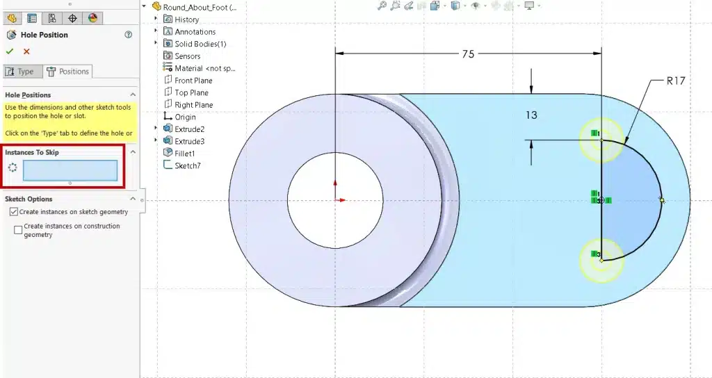
If there are specific instances of the hole that you don’t want to create, you can skip them. In order to do this, click on Instances to Skip and select the hole skip. This option allows you to be selective in the hole creation process.

Step 10:
After we’ve configured all the parameters and positions, click OK to generate the holes according to your specifications.

Step 11:
Save the part.

Step 12:
When we delete the Hole Wizard Feature, we can retain the hole position sketch by deselecting the Delete absorbed features.

Conclusion
In conclusion, leveraging the advanced features of the Hole Wizard Tool can greatly streamline your hole creation process, offering precise control and flexibility. To further optimize your CAD design workflow, check out our blog on “Automatically Optimize Resolved Mode | SOLIDWORKS,” which provides additional strategies for enhancing performance and efficiency in your designs.
About i GET IT by Tata Technologies
i GET IT by Tata Technologies is online learning platform for mechanical engineers and designers. It has extensive 2000+ range of courses, 8+ job role certifications and coverage of 20+ domain topics that makes it a comprehensive hub for engineering education. By offering specialized certifications and personalized learning paths, we ensure that learners not only acquire knowledge but also develop expertise in their chosen fields.
For more tech tips and in-depth eLearning for SolidWorks, including this and new courses on other design solutions, please visit i GET IT . You can sign up and get a FREE Subscription to our informative Newsletter.
Manjunath
Meet Manjunath Goshanatti, a versatile professional excelling in CAD expertise, data science, and technical content writing. With a keen eye for detail and a knack for simplifying complex concepts, Manjunath delivers authentic content on mCAD software solutions.
Related Posts
What is Fluid Mechanics? – Introduction, Laws & Equations
January 7, 2026
179 views
What Is AutoCAD Software? Uses, Features & Practical Examples
December 18, 2025
289 views
Independent Front Wheel Suspension – Types, Benefits & Working
November 10, 2025
419 views
What is PLM? – Product Lifecycle Management [Detailed Guide]
October 9, 2025
470 views
Lead-Acid vs. Lithium-Ion Batteries: Key Differences & Best Uses
June 13, 2025
670 views
Find
Categories
Latest Posts
What is Fluid Mechanics? – Introduction, Laws & Equations
January 7, 2026What Is AutoCAD Software? Uses, Features & Practical Examples
December 18, 2025Independent Front Wheel Suspension – Types, Benefits & Working
November 10, 2025Popular Tags
3DEXPERIENCE
ACES
Aerospace
Aircraft Cabin
Assembly
autocad
autodesk
Autodesk Inventor
Business
CAD
CAD courses
CAD Drawings
CAD Drawing view
CAM
cam and follower
Career
cars
catiav5
CATIA V5
Chamfer
corner relief
CREO
design engineering
Design Engineers
dimensioning
Engineering Education
ev
EV Engineer
GD&T
inventor
Mechanical engineering
NX
NX 2306
Online Certification
product design
PTC
Sketcher
Sketching
Solid Combine
solidworks
Spinal Bend
tech
tech tips
threaded stud work
Upskilling


