Sketch Checking in Siemens Designcenter: A Quick Tech Tip
September 30, 2026 2026-09-30 13:22Sketch Checking in Siemens Designcenter: A Quick Tech Tip

Sketch Checking in Siemens Designcenter: A Quick Tech Tip
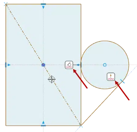
Sketch Checking in Siemens Designcenter is a powerful feature that helps identify and resolve sketch issues before they impact your design. In CAD design, a sketch may look perfectly fine at first glance—but the real problems often appear later, when features fail or behave unexpectedly. These issues are often caused by incorrect or missing geometric relationships, disconnected geometry, or tiny unintended curves.
Identifying these problems manually can be time-consuming and frustrating, especially in complex designs. This is where Sketch Checking becomes an essential tool. It helps designers quickly analyze sketch geometry, validate relationships, and detect issues that could impact downstream modeling operations. By working alongside Display Relations, it also provides a clear visual understanding of how different sketch elements are connected and constrained.
From basic checks like verifying connections between lines and curves to more advanced validations such as identifying tangent conditions, concentric geometry, or tiny curves, Sketch Checking helps designers create cleaner and more reliable sketches. Whether you are a beginner learning sketch fundamentals or an experienced designer working on complex models, this feature plays a key role in improving sketch quality and reducing the likelihood of modeling errors.
Table of Contents
What is Sketch Checking in Siemens Designcenter?
Sketch Checking in Siemens Designcenter is a built-in command that helps designers identify and resolve issues within a sketch. It provides a systematic way to analyze sketch geometry, evaluate relationships between elements, and detect conditions that may affect sketch quality or downstream modeling operations.
Instead of manually inspecting each line, arc, or relationship, Sketch Checking analyzes the sketch according to the selected checking options and highlights potential issues such as incorrect relationships, disconnected geometry, or tiny curves. This makes it easier to understand how the sketch is defined and where improvements are needed.
When used together with Display Relations, designers can visually inspect the relationships between sketch entities directly in the Graphics window. This improves clarity and helps in identifying potential issues before moving forward in the design process.
Overall, Sketch Checking helps designers identify sketch issues before further modeling and can reduce the chances of errors in later stages.
If you’re new to Siemens NX, you can also explore our guide on What is NX CAD Design Software? – Introduction 101 to understand the fundamentals before diving deeper.
Key Capabilities of Sketch Checking
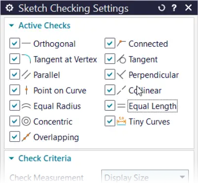
Sketch Checking in Siemens Designcenter supports the validation of multiple geometric conditions and relationships within a sketch. It helps ensure that sketch elements are correctly defined and behave as expected during modeling.
Some of the key capabilities include:
- Orthogonal – Identifies geometry that should satisfy an orthogonal relationship.
- Parallel – Checks whether selected geometry maintains a parallel relationship.
- Perpendicular – Ensures that geometry meets perpendicular conditions.
- Collinear – Verifies if linear elements lie along the same line.
- Tangent – Checks tangency between curves or sketch entities.
- Tangent at Vertex – Validates tangency at a shared vertex between elements.
- Point on Curve – Confirms whether a point is correctly positioned on a curve.
- Connected – Identifies whether sketch entities are properly connected.
- Concentric – Ensures circular elements share a common center.
- Equal Radius – Identifies arcs or circles that should have equal radii.
- Equal Length – Checks whether lines or curves have equal lengths.
- Tiny Curves – Detects very small or unintended curves that may lead to sketch or modeling issues.
Workflow: How to Use Sketch Checking
To begin, activate the required sketch from the Part Navigator and open the Sketch Navigator. This allows you to access and manage all sketch elements and their relationships.
Next, use Display Relations from the Solve group or the sketch ribbon, depending on your interface version, to visualize the relationships between sketch entities directly in the Graphics window. This step provides a clearer understanding of how different sketch elements are related and helps in identifying potential issues.
Once the relationships are visible, select Sketch Checking from the Solve group. The system analyzes the sketch and highlights potential issues using visual indicators. These may include missing or incorrect relationships, disconnected geometry, tiny curves, or other conditions that can impact sketch quality.
You can then select an identified issue in the Graphics window or Sketch Navigator to inspect the related geometry and review available correction or ignore options. Corrections can be applied based on the type of issue detected.
After resolving the identified problems, it is recommended to re-run Sketch Checking to confirm that the identified issues have been addressed before proceeding with further modeling operations.
Benefits of Using Sketch Checking
Using Sketch Checking in Siemens Designcenter helps designers improve the overall quality and reliability of their sketches. By identifying issues early in the design process, it reduces the chances of errors during later modeling stages.
Some key benefits include:
- Early issue detection – Helps identify sketch problems before they impact downstream operations.
- Better understanding of relationships – Provides clear visibility into how sketch entities are connected and constrained.
- Detection of unwanted geometry – Identifies issues such as tiny curves or unintended elements that may affect modeling.
- Improved sketch accuracy – Ensures that geometry and constraints are correctly defined.
- Reduced modeling errors – Minimizes failures in features caused by incomplete or incorrect sketch definitions.
- Simplified validation process – Combines multiple checks into a single, efficient workflow.
Want to see how this works in action?
Watch the full tutorial to see how it works step by step in real-time.
Explore our YouTube channel with 250+ videos covering CAD and design topics, created to help you build stronger skills and learn concepts in a structured, practical way.
Key Takeaway
Sketch Checking in Siemens Designcenter provides an efficient way to validate sketch geometry and relationships before moving to downstream modeling operations.
By identifying conditions such as orthogonal, tangent, parallel, concentric, connected, perpendicular, collinear, equal radius, equal length, point-on-curve, tangent-at-vertex, and tiny curves, it helps designers detect and resolve potential issues early in the design process.
By helping ensure that sketches are accurate, well-defined, and more reliable, Sketch Checking contributes to improved model quality and reduces the likelihood of failures in later stages of design.
Explore the Siemens NX Training Bundle by Tata Technologies
Learn Siemens NX from sketching fundamentals to advanced modeling, assemblies, drafting, and simulation — and build practical skills to create accurate, reliable designs using industry-standard workflows.
Explore ProgramContact UsFAQs – Sketch Checking in Siemens NX
This message means the sketch has not been solved or updated by the system. It usually happens when evaluation is turned off or delayed, so NX hasn’t processed the constraints and geometry yet.
A sketch is fully defined when all its geometry is controlled using dimensions and constraints, leaving no movable elements. NX indicates this using status indicators or color coding in the Sketch Navigator.
You can use Display Relations to visualize constraints directly in the Graphics window. Additionally, the Sketch Navigator (Relations tab) shows all applied constraints and dimensions.
Sketch Checking is a tool that helps identify errors, missing constraints, and geometric inconsistencies in a sketch. It automatically highlights issues and suggests corrections to improve sketch quality.
Tiny curves are very small or unintended sketch elements created during trimming or editing. These can cause issues in operations like extrusion or filleting and should be removed or corrected.
Common causes include:
- Missing constraints
- Over-constrained geometry
- Disconnected entities
- Conflicting relationships
NX classifies sketches as under-constrained, well-constrained, or over-constrained based on these conditions.
You can fix errors by:
- Running Sketch Checking
- Reviewing issues in the Sketch Navigator
- Adding or correcting constraints
- Removing unnecessary geometry
- Under-constrained: Sketch elements can still move (not fully defined)
- Over-constrained: Too many constraints cause conflicts
A well-constrained sketch is stable and behaves predictably.
Both tools are powerful, but Siemens NX offers advanced sketch solving, automated relation detection, and tools like Sketch Checking, making it more suitable for complex engineering workflows. However, SolidWorks is often preferred for simpler designs and ease of use.
Eric Bansen
Related Posts
Manufacturing Process Planning: Step-by-Step Guide for Engineers
How to Insert a Sketch Picture in SOLIDWORKS (Step-by-Step Guide)
CATIA V5 Tutorial – How to Use Note Object Attribute with Ditto
Geneva Mechanism Explained: Working Principle, Design & Applications
What is Fluid Mechanics? – Introduction, Laws & Equations
Find
Categories
Latest Posts
Sketch Checking in Siemens Designcenter: A Quick Tech Tip
September 30, 2026Manufacturing Process Planning: Step-by-Step Guide for Engineers
September 10, 2026Popular Tags