Engineering CAD Drawing Views: Learn Basics, Types & Examples
April 10, 2024 2024-05-15 16:14Engineering CAD Drawing Views: Learn Basics, Types & Examples
Engineering CAD Drawing Views: Learn Basics, Types & Examples
Engineering drawing views serve as the foundation of technical design processes, offering a visual representation of objects or systems from various angles. They play a pivotal role in facilitating communication, visualization, and comprehension among professionals in engineering, design, and manufacturing domains. Proficiency in CAD drawing views is paramount for individuals engaged in disciplines such as engineering, architecture, product design, and manufacturing.
Nowadays, Computer Aided Designing (CAD) has not only brought enough ease and flexibility in 3D design but also, in drafting or 2D Detailing as well in which generating the Engineering Drawing views or the CAD drawing views in layman terms, is of paramount importance. So, in this comprehensive guide, we will delve into the intricacies of engineering drawing views, examining their types, principles, and significance in the design and manufacturing realms
Table of Contents
Types of CAD Drawing Views:
We will now discuss various types of Engineering drawings or CAD Drawing views including: Orthographic Projection, Axonometric Projection, Sectional Views, Auxiliary Views, Detailed Views, Broken Views and Exploded View.
1. Orthographic Projection
This fundamental method represents a three-dimensional object in a twodimensional plane through a series of 2D views taken from different perspectives. In this technique, the object is projected onto a flat surface using lines that are perpendicular to that surface. This creates a sequence of 2D views, with each view presenting one side of the object as though it were transparent, allowing the viewer to observe it directly from a specific angle. The six principal orthographic views include Front view, Top view, Bottom view, Right view, Left view and Rear view.
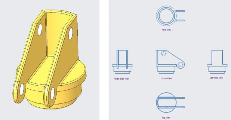
Note that consistent alignment and orientation of views ensure clarity and ease of interpretation across multiple drawings. So, for the same, standard conventions as first angle and third angle projection methods maintain uniformity in engineering drawings.
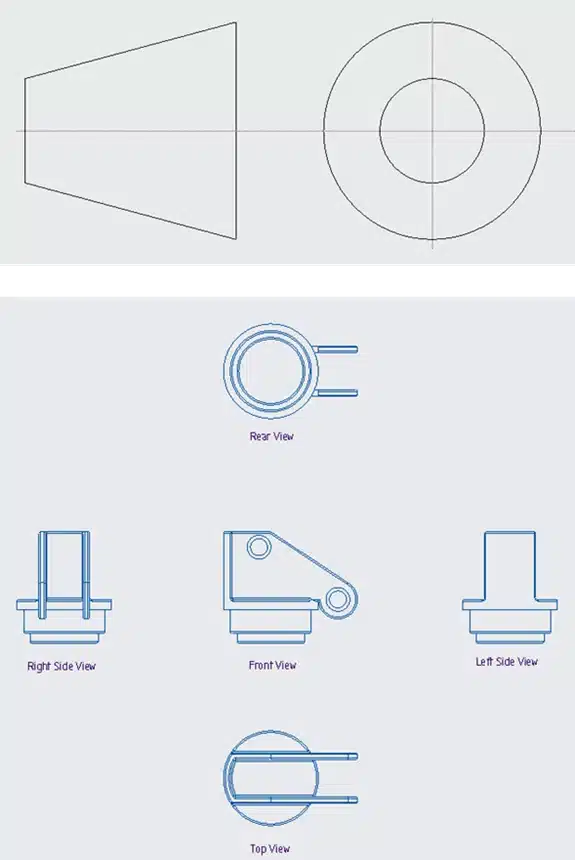
Figure 2 is referred to as first-angle projection. In this method, the top view is positioned below the front view, while the right view is situated to the left of the front view, and so forth. Primarily utilized in India, Europe, the ISO standard follows this convention.
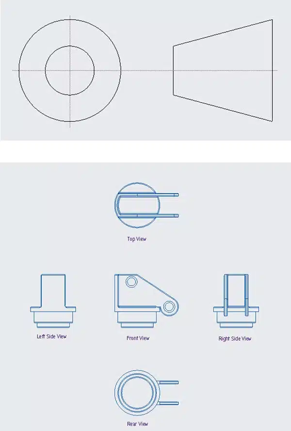
Figure 3 depicts the third-angle projection. In this arrangement, the right
view is located to the right, the top view is positioned above the front view, and so on. This
approach is particularly prevalent in the US and Canada
2. Axonometric projection:
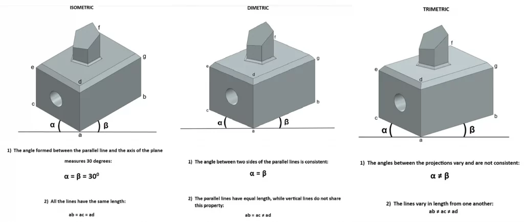
This is a parallel projection technique, finds application in technical drawings, architecture, and computer graphics for representing three-dimensional objects in two dimensions. Unlike isometric projection, which uniformly shortens all three axes, axonometric projections allow for varying degrees of foreshortening along each axis.
Various types of axonometric projections exist, including:
- Isometric Projection: This type maintains uniform foreshortening along all three axes. Isometric projection offers a pictorial representation of three-dimensional objects in two dimensions. In isometric projection, the three dimensions of an object are equally shortened, resulting in a representation where the object’s length, width, and height are all scaled proportionally in the same ratio. So, unlike orthographic projection, isometric projection displays all three dimensions in a single view, enhancing accuracy in visualizing shape and size.
Dimetric Projection: In dimetric projection, two axes are foreshortened at equal
angles, while the third is shortened at a different angle.Trimetric Projection: Trimetric projection involves distinct foreshortening angles for
all three axes
3. Sectional Views
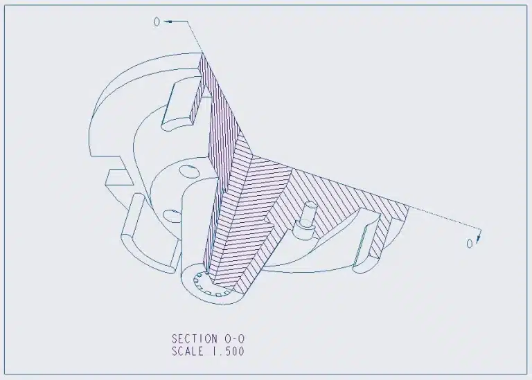
Sectional views provide insights into the internal structure of an object by cutting it along a specific plane and exposing hidden features. Variants such as full section, half section, local section (cut-out section) and offset section offer detailed perspectives on different aspects of the object's design.


4. Auxiliary Views:
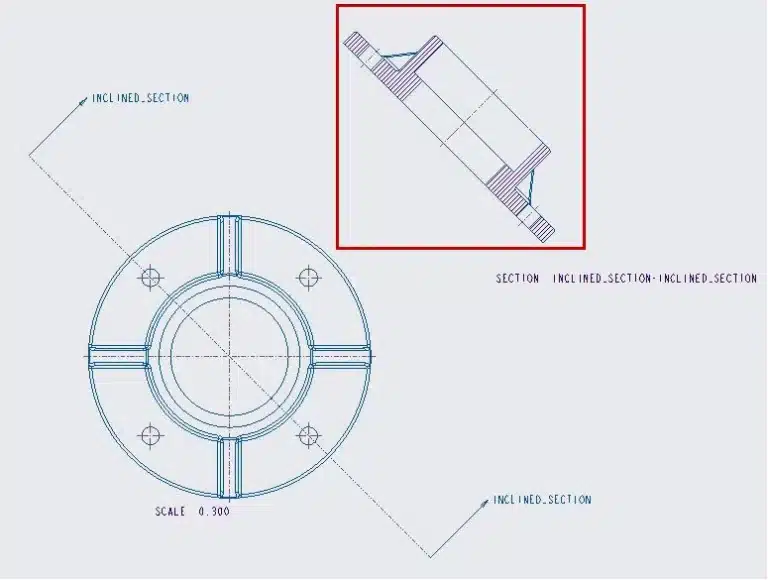
Auxiliary views serve as supplementary perspectives to depict the true shape and size of features not parallel to principal orthographic planes. They aid in clarifying complex geometries or inclined surfaces that are challenging to represent in primary views.
5. Detailed Views:
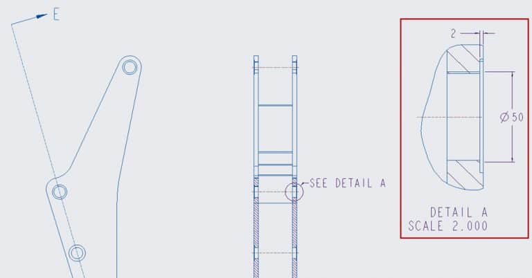
Detailed views magnify specific areas of interest within a larger drawing, offering a more intricate representation of features or components. They enable engineers and designers to focus on critical elements without cluttering the main drawing.
6. Broken Views:
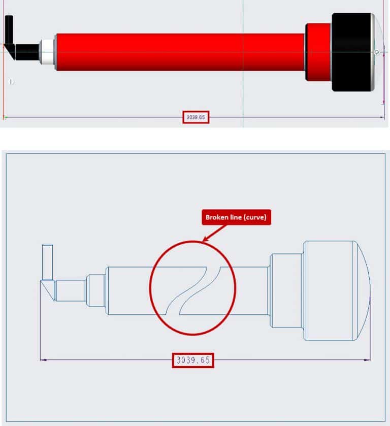
Broken views in CAD (Computer-Aided Design) are graphical representations of objects that are partially obscured or interrupted, typically due to their large size or complex shape. These views are created by breaking the object into segments, allowing designers to display specific details or features of interest more clearly.
7. Exploded View:
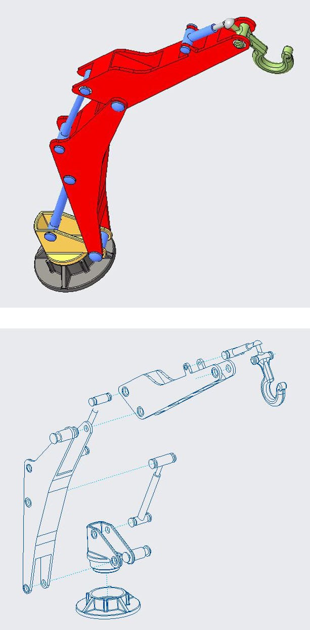
It aims to depict the components of an object or structure, showcasing their spatial arrangement and assembly sequence. In this representation, individual components are separated and displayed apart from their assembled position, often accompanied by lines or arrows indicating their original placement
Principle Tools of Engineering/CAD Drawing Views
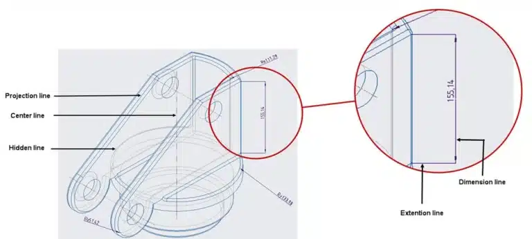
1. Projection Lines: The prevalent form is a continuous line, also referred to as a Projection line, which signifies the tangible boundaries of an object. Projection lines project points from the object onto the drawing plane.
2. Hidden Lines: Hidden lines represent features obstructed from view.
3. Centerlines: Centerline serve the purpose of indicating holes and the axis or symmetry of
cylindrical or symmetrical features. Displaying symmetry can decrease dimensionality and
enhance the visual appeal of the drawing, thereby making it easier to comprehend.
4. Dimension lines: Extension lines and Scaling: Extension lines annotate the item being measured. The dimension line features two arrowheads positioned between the extension lines, with the measurement displayed above (or inside, as depicted in the image below) the line.
Note: Accurate dimensioning and scaling are essential to convey the size, shape, and
tolerance of objects effectively. Strategically placed dimensions facilitate manufacturing
processes and minimize ambiguity.
5. Cutting plane line or sectional view line: In a cutout view, the cutting plane lines indicate the path of the cut. In this example, the A-A cutting line reveals the cutouts within the view:

Importance of Engineering Drawing Views
1. Communication: Engineering drawing views serve as a universal language for conveying design intent, specifications, and manufacturing requirements among interdisciplinary teams and stakeholders.
2. Visualization and Analysis: Multiple perspectives provided by engineering drawing views enable visualization, analysis, and identification of potential design flaws or optimization opportunities.
3. Manufacturability: Comprehensive engineering drawing views offer detailed instructions for machining, assembly, and quality control, reducing errors and ensuring consistency in manufactured products.
4. Documentation and Compliance: Engineering drawing views serve as official
documentation of the design, necessary for regulatory compliance, patent applications, and quality certifications, providing a comprehensive record of the product lifecycle.
How can you improve your CAD drawings skills?
Proficiency in engineering drawing views is essential for professionals involved in design, engineering, and manufacturing industries. Understanding the types, principles, and significance of engineering drawing views empowers engineers and designers to communicate design intent effectively, visualize complex geometries accurately, and ensure manufacturability and compliance with industry standards. As technological advancements continue, digital tools and software augment traditional drafting techniques, offering opportunities for collaboration, efficiency, and innovation in engineering design processes.
To enhance your proficiency in CAD drawings and gain a comprehensive understanding of its various aspects, consider enrolling in CAD courses offered by i GET IT – Tata Technologies. With expert-led instruction and hands-on learning experiences, these courses provide the knowledge and skills needed to excel in CAD design and advance your career in engineering. Start your learning journey today and unlock your full potential in CAD drawing and design.
How i GET IT by Tata Technologies can help you?
i GET IT is Tata Technologies premier eLearning solution tailored to enhance the proficiency of mechanical and design engineers in utilizing today’s leading MCAD (Mechanical Computer Aided Design) applications and honing their design skills.
Explore our extensive library of courses covering AutoDesk, AutoCAD, SOLIDWORKS, Catia V5, and a host of other cutting-edge design solutions. With i GET IT, you can access in-depth e-learning modules, tech tips, and new courses designed to sharpen your skills and stay ahead in the ever-evolving field of engineering design.
Embark on your upskilling journey today by visiting https://www.myigetit.com and take the next step towards mastering CAD software and advancing your career.
For any inquiries or assistance, please don’t hesitate to contact us at igetitsupport@tatatechnologies.com.
Unlock your potential with i GET IT. Start learning, start achieving.
Prateek Potnis
Related Posts
Series & Parallel Hybrid Vehicles: Are they Outsmarting EVs?
What is Computer Aided Manufacturing (CAM)? [Detailed Guide]
Top 5 Mechanical Design Engineer Courses by Tata Technologies
What is Single Line Diagram? – Meaning, Importance & Example
Is Mechanical Engineering a Good Career for the Future?
Find
Categories
Latest Posts
Popular Tags


