How to Use Corner Relief in Catia V5
March 5, 2024 2024-11-11 14:20How to Use Corner Relief in Catia V5
Overview
In this article, we will explain how to use corner relief in Catia V5 with the help of user profile. This functionality serves to alter sharp corners or edges, especially in Mechanical or Industrial design, playing a pivotal role in transforming design ideas into practical, manufacturable, and visually appealing products.
Please accept the cookies to see this video.
Please follow the below steps to use corner relief in Catia V5:
Step 1:
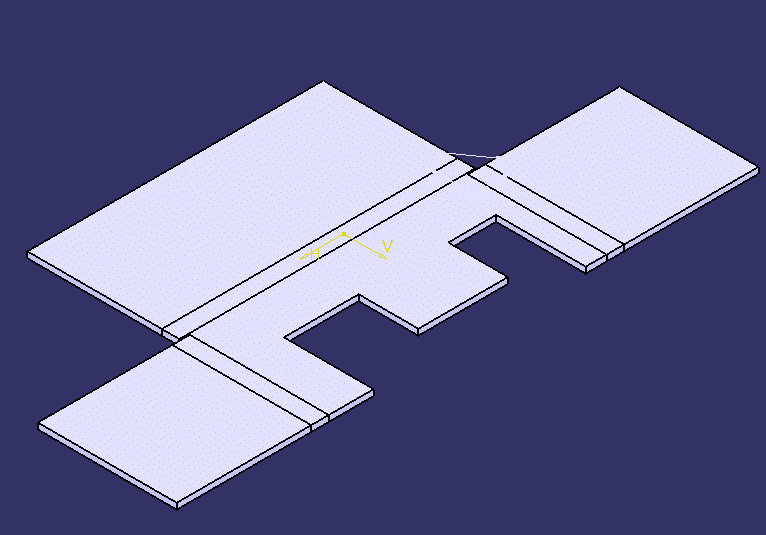
Open the part file named corner-relief2.CATPart to begin your work.
Step 2:
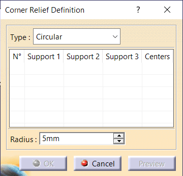
Select ‘Insert’, then go to ‘Cutting’, and choose ‘CornerRelief’ to open the Corner Relief Definition dialog.
Step 3:
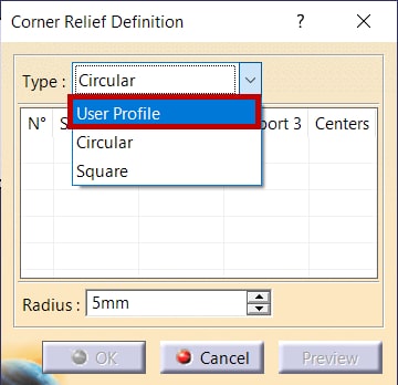
Navigate to the Corner Relief Definition dialog and elevate your selection by opting for “User Profile” from the type list.
Step 4:
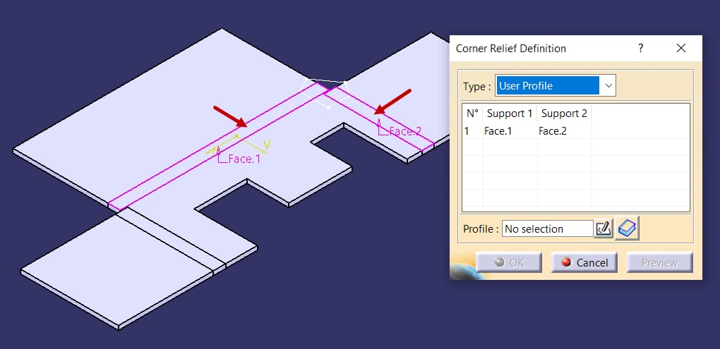
Select the bends identified in the illustration, designating them as Support 1 and Support 2 for further processing.
Step 5:
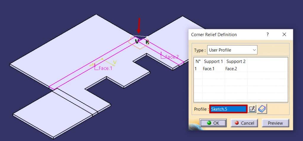
Choose the polygon in the Graphics window as the sketch for corner relief creation and observe a preview of the relief.
Step 6:
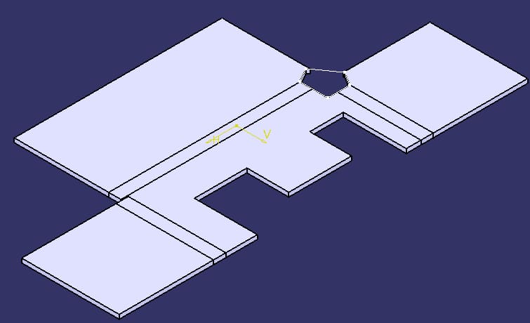
Generate a localized corner relief by initiating the necessary steps within the design environment to enhance the specific geometric features effectively.
Step 7:
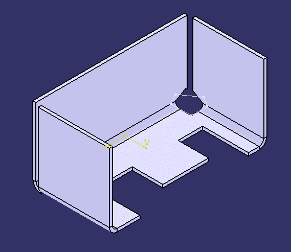
Activate the Fold/Unfold command from the Views toolbar to seamlessly fold the sheet metal part in the design process.
About i GET IT
i GET IT is our Tata Technologies eLearning solution designed to teach engineers how to be better at using today’s leading MCAD (Mechanical Computer Aided Design) applications and design skills.
For more tech tips and in-depth eLearning for Catia V5, including this and new courses on other design solutions, please visit i GET IT. You can sign up and get a FREE Subscription to our informative Newsletter.
Start your Upskilling Journey Now! Visit our Plans Pages –
If you should have any questions, please reach out to iproducts@tatatechnologies.com or igetitsupport@tatatechnologies.com for help.
If you like our Tech Blogs do share them using the following share this post icon.
Vinay
Vinay Kumar G is a dynamic professional renowned for his mastery in CAD and technical content creation. With an unwavering commitment to precision and navigating the complex terrain of design with CAD proficiency, he is your go-to expert for insightful content revolving around cutting-edge mCAD software solutions.
Related Posts
Lead-Acid vs. Lithium-Ion Batteries: Key Differences & Best Uses
June 13, 2025
113 views
Top AutoCAD 3D Commands & Shortcuts with Examples
April 9, 2025
638 views
What is Engineering Mechanics? – Introduction 101
March 10, 2025
544 views
How to Create Stitch Weld in Weldments using Autodesk Inventor?
November 15, 2024
343 views
How to Create Blend Curve on Surface using Siemens NX?
November 9, 2024
659 views
Find
Categories
Latest Posts
Popular Tags
3DEXPERIENCE
ACES
Aerospace
Aircraft Cabin
Assembly
autocad
autodesk
Autodesk Inventor
Business
CAD
CAD courses
CAD Drawings
CAD Drawing view
CAM
cam and follower
Career
cars
catiav5
CATIA V5
Chamfer
corner relief
CREO
design engineering
Design Engineers
dimensioning
Engineering Education
ev
EV Engineer
GD&T
inventor
Mechanical engineering
NX
NX 2306
Online Certification
product design
PTC
Sketcher
Sketching
Solid Combine
solidworks
Spinal Bend
tech
tech tips
threaded stud work
Upskilling


