What is GD&T and Why is it Important for Design Engineers?

What is Geometric dimensioning and tolerancing and Why it is important
GD&T Tech

What is GD&T and Why is it Important for Design Engineers?

In today’s highly competitive industry, companies are constantly striving to improve their quality standards and manufacturing processes. One way they achieve this is by implementing Geometric Dimensioning and Tolerancing (GD&T) principles. GD&T is a universal language that allows engineers and manufacturers to communicate design and production requirements accurately. If you want to enhance your knowledge and skills in GD&T, this ultimate guide to GD&T is here to help you. Whether you are a beginner or an experienced professional looking to expand your expertise, this guide will provide you with valuable insights into GD&T and its applications.

Table of Contents

What is GD&T?

GD&T also known as Geometric Dimensioning and Tolerancing, facilitates precise communication of design specifications and tolerances within engineering. This systematic approach empowers design engineers and manufacturers to effectively manage variations in manufacturing processes, ultimately ensuring superior outcomes, precision designing and solid product quality.

GD&T is a standardized system of symbols and rules to specify the geometric characteristics of an engineering design. It ensures that parts and assemblies are manufactured and inspected correctly, reducing errors, and improving overall quality. GD&T is vital in industries where precision is crucial, such as aerospace, automotive, and manufacturing.

Why GD&T is Important for Design Engineers?

GD&T is important because it’s the engineering language for precise parts. GD&T ensures interchangeability, simplifies manufacturing, and minimizes assembly errors – leading to efficient, high-quality designs.

Have you ever tried writing a captivating story without understanding grammar? It can be frustrating and confusing for both you and your reader. The same applies to engineering design! Before diving into complex design software, mastering Geometric Dimensioning & Tolerancing (GD&T) equips you with a critical skill – the language of engineering. Just like mastering grammar unlocks clear and effective writing, GD&T empowers you to communicate your design intent precisely and efficiently. It’s the foundation for creating flawless designs and ensuring everyone involved – engineers, manufacturers, and assemblers – are on the same page. Imagine the efficiency and reduced errors when everyone speaks the same language – the language of GD&T!

Watch the recording of our exclusive webinar with the renowned expert and our GD&T course author Mark Foster explaining fundamentals and core principles of GD&T.

Key Principles of GD&T

To fully grasp GD&T, it is essential to understand its core principles. These principles include datums, geometric tolerances, form controls, orientation controls, and location controls. Each principle plays a key role in defining and controlling the geometric aspects of a part or assembly. 

Understanding datums, which are reference points for dimensional measurements, is fundamental in GD&T. Geometric tolerances, on the other hand, specify the allowable deviation from the perfect geometry of a part. Form controls ensure that the shape of a feature is within specified limits, while orientation controls dictate the allowable tilt or angle of a feature. Location controls define the position of features in relation to each other or a reference point, ensuring proper alignment and fit of components.

Lets understand the these principles in details. Below are the key principles of GD&T:

1. Datums: The cornerstone of GD&T, datums are theoretically perfect, geometric features that act as reference points for all dimensional measurements and tolerance applications. Selecting the appropriate datums is crucial, as they influence how all other GD&T specifications are interpreted. Common types include features like faces, centerlines, and datums established by other features.

2. Geometric Tolerances: These define the allowable variation in a feature’s form (shape) or runout (concentricity and cylindricity) compared to its ideal geometry. Unlike simple size tolerances, geometric tolerances account for deviations that wouldn’t be captured by traditional +/- tolerances. This allows for more precise control over a part’s functionality and assembly.

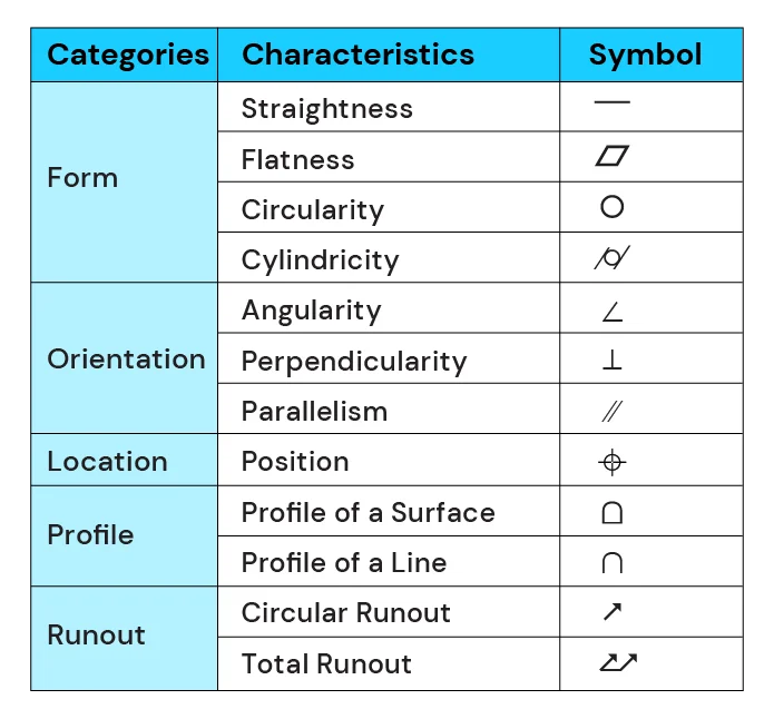
3. Form Controls: Focusing on a feature’s shape, form controls specify acceptable limits for deviations from a perfect form. Common examples include:

a.  Straightness: Controls how much a feature deviates from a perfect straight line.

b. Flatness: Defines the allowable variation in a surface’s flatness, ensuring it remains within a specified tolerance zone.

c. Circularity: Specifies the allowable deviation from a perfect circle for a circular feature.

d. Cylindricity: Controls how much a cylindrical feature deviates from a perfect cylinder, encompassing straightness, roundness, and cylindricity variations.

4. Orientation Controls: These dictate the permissible tilt, angularity, or parallelism of a feature relative to a datum. Orientation controls ensure proper alignment and functionality between parts during assembly. Examples include:

a. Straightness: Like form control straightness, but in this case, it controls how much a feature’s axis deviates from a perfect straight line relative to a datum.

b. Angularity: Defines the allowable deviation from a specified angle between a feature’s surface and a datum.

c. Parallelism: Controls how much a feature’s surface deviates from being perfectly parallel to a datum.

5. Location Controls: They define the allowable variation in a feature’s position (e.g., location, concentricity, and runout) in relation to a datum or other features. Location controls ensure proper fit and function during assembly. Common examples include:

a. Positional Tolerance: Specifies a zone within which the center of a feature must reside relative to a datum.

b. Concentricity: Controls how much the center-points of two or more circular features deviate from a common center-point.

c. Runout: Defines the allowable variation in the circularity or cylindricity of a feature about a datum axis.

By effectively applying these GD&T principles, engineers can achieve a high degree of precision and clarity in their designs. This leads to the creation of interchangeable parts, streamlined manufacturing processes, and ultimately, high-quality products.

What is GD&T Symbols?

GD&T symbols is used to convey specific instructions and requirements for the design and manufacturing process. Symbols such as position, flatness, perpendicularity, and concentricity provide precise details on how a part or assembly should be measured, aligned, and inspected. 

Each GD&T symbol has a unique meaning and application, allowing engineers and manufacturers to communicate complex geometric requirements effectively. For example, the position symbol specifies the allowable deviation from a true position, ensuring that a feature is located accurately. Understanding these symbols is crucial for interpreting engineering drawings correctly and producing parts that meet the desired specifications. 
 

GD&T Symbols Chart

What is GD&T used for?

In this section, we explore the fundamental applications or use cases of Geometric Dimensioning and Tolerancing (GD&T) in engineering design, manufacturing, and quality control. Understanding the purpose and significance of GD&T is essential for ensuring precise communication of design intent, achieving manufacturing accuracy, and maintaining quality standards throughout the product lifecycle. Let's delve into the multifaceted utility of GD&T across various domains.  application, allowing engineers and manufacturers to communicate complex geometric requirements effectively. For example, the position symbol specifies the allowable deviation from a true position, ensuring that a feature is located accurately. Understanding these symbols is crucial for interpreting engineering drawings correctly and producing parts that meet the desired specifications. 

Use of GD&T in Engineering Design

Engineers utilize GD&T to communicate design intent effectively. By explicitly specifying dimensions, tolerances, and geometric requirements, they ensure that their designs are accurately interpreted and translated into physical parts. GD&T enables engineers to control the form, fit, and function of their designs, guaranteeing consistency and reproducibility. 

Moreover, GD&T empowers engineers to design parts that are more robust and durable. By considering the functional requirements and applying appropriate geometric controls, engineers can optimize the design for manufacturability and assembly. This leads to improved product performance, reduced failure rates, and increased customer satisfaction. 

Use of GD&T in Manufacturing

What is gd&t in manufacturing? The manufacturing industry heavily relies on GD&T to ensure that parts and assemblies are produced with precision and accuracy. By employing GD&T principles, manufacturers can control dimensions, tolerances, and geometric features, resulting in better product quality, reduced costs, and improved overall efficiency. 

One of the key benefits of GD&T in manufacturing is its ability to enhance the interchangeability of parts. With precise geometric controls, manufacturers can ensure that components from different suppliers fit together seamlessly, reducing the need for costly modifications or rework. This not only streamlines the production process but also minimizes the risk of assembly errors and improves overall product performance. 

Use of GD&T in Quality Control and Assurance

In quality control and assurance, GD&T plays a crucial role in inspecting and verifying manufactured parts and assemblies. By using GD&T symbols and measurements, quality control professionals can quickly identify deviations from the design specifications and determine if they fall within acceptable limits. GD&T aids in maintaining product consistency and adherence to quality standards. 

Additionally, GD&T facilitates the implementation of statistical process control (SPC) techniques. By monitoring key geometric characteristics and their variations, manufacturers can identify trends and patterns, enabling them to make data-driven decisions for process improvement. This proactive approach to quality control helps to prevent defects, reduce waste, and enhance overall product reliability. 

How to Enhance Your GD&T Skills?

Whether you are a mechanical engineer, a quality control technician, or someone seeking to enhance their knowledge in design and manufacturing, investing in GD&T training can greatly benefit your career. Keep in mind the importance of selecting the right training program and continuously applying the learned principles in your professional practice. With the knowledge gained from GD&T training, you can contribute to the success of your organization and become a valuable asset in the industry. 

Our GD&T Training Course provides a comprehensive and interactive learning experience designed to equip you with the skills and knowledge to confidently apply GD&T principles in your field. Here’s the highlight of our course.

Modular Structure: Our course is divided into 6+ modules, covering both basic and advanced GD&T concepts. 

In-depth Learning: Benefit from instructor-led video lessons totaling over 40 hours of training. 

Interactive Learning: Engage with dynamic multimedia modules and an interactive learning dashboard to track your progress. 

Expert Support: Gain valuable insights through technical webinars and receive expert feedback on your learning. 

Personalized Learning Path: We provide a personalized learning path with assignments to solidify your understanding. 

Invest in your future and become a GD&T Expert!

About i GET IT

i GET IT is a e-learning initiative started by Tata Technologies that offers a comprehensive training solution tailored to the latest MCAD/PLM applications and industry skills, featuring robust customization tools, assessment capabilities, and learning management features. Our training programs deliver tangible results, enhancing productivity and minimizing design errors in manufacturing by elevating design quality. 

Access over 2,000+ self-paced training programs, live technical sessions, and certifications curated and delivered by Tata Technologies. Explore a wide range of topics, including Autodesk, Siemens PLM, 3DEXPERIENCE, CATIA, SOLIDWORKS, CREO, and essential industry skills. Customers can also create and tailor their own engineering training courses using our extensive content library, with the ability to assign, analyze, and manage teams efficiently through robust reporting features. Experience the power of i GET IT Learning and unlock your team’s full potential in engineering design and beyond. 

LMS
logo

Autodesk Training Subscription

1010

OR

Verify email

Start your 3 days free trial now


Already have an account? Sign In

By clicking the button above, you accept our terms of use and privacy policy.

LMS
logo

Autodesk Training Subscription

1010

OR

Verify email


(Ensure popup is allowed for this site)

Pay now, get full term access


Already have an account? Sign In

By clicking the button above, you accept our terms of use and privacy policy.

LMS
logo

Sign In

Have Organization Sign In?  Use Single Sign On

Don’t have an account? Sign Up

OR

logo

Sign Up

Already a user? Sign In

Verify

(Ensure popup is allowed for this site)

OR


Have Organization Sign In?   Use Single Sign On

By Registering you agree to the Terms of Use and Privacy Policy.

logo

Single Sign On

If your company has single sign-on set-up with i GET IT, enter your company's web address to access your unique login page. The format needs to be as such: "domainname.com".

(Ensure popup is allowed for this site)

Not an enterprise user?Sign In
logo

Forgot Password

Enter your email and we'll send you instructions on how to reset your password.