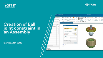
How to create Ball joint in an Assembly | NX2306 version
October 18, 2023 2023-10-25 15:43How to create Ball joint in an Assembly | NX2306 version
How to create Ball joint in an Assembly | NX2306 version
Overview
In this TechTip you will learn about how to create Ball joint in an Assembly using Nx2306 version. A Ball joint is similar to a Spherical joint in the Motion application and removes three degrees of freedom. You can rotate the constrained component about all three axes and will not be able to translate along any axis.
You can use the part file from the – Download or Open ball_joint_tripod_adapter.zip File. (Active Subscription is required)
(accept cookies to see the video)
Please follow the below steps to achieve the required result –
Creation of Ball joint constraint in an assembly.
Step 1
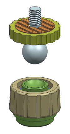
Open ball_joint_tripod_adapter\ball_joint_tripod_adapter_assembly.prt.
Step 2
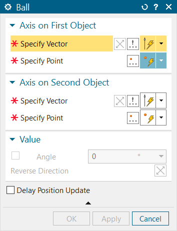
Select Assemblies tab >Position group >Joints and Couplers > Ball to display the Ball dialog box.
Step 3
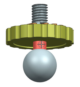
To specify the vector for constraining the axis on the first object, choose “Specify Vector” from the options in the “Geometry to Constrain > Axis on First Object” dropdown menu. Then, select a cylindrical face on the component called “ball_joint.“
Step 4
To select the “Specify Point” option in the “Geometry to Constrain > Axis on First Object” dropdown menu, click on “Point Dialog” to open the “Point” dialog box.
Set the drop-down at the top of the Point dialog to Arc/Ellipse/Sphere Center.
Pick the spherical face as shown to define its center as the point.
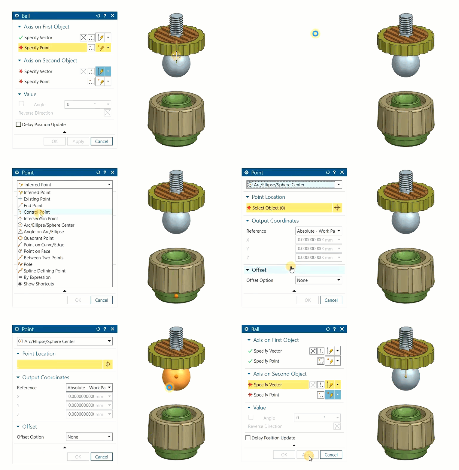
Step 5
Click OK to return to the Assembly Constraints dialog.
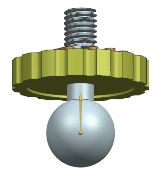
Step 6
To choose the “Specify Vector” option in the “Geometry to Constrain > Axis on Second Object” dropdown menu, you should select a cylindrical face on the component called “head.”
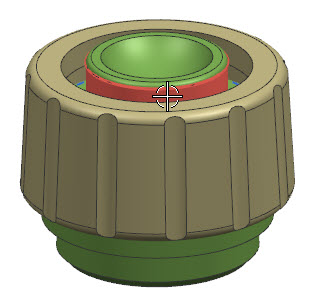
Note: The vector should point in the same direction as that you defined for the First Object. If it does not, click Reverse Direction.
Step 7
To select the “Specify Point” option in the “Geometry to Constrain > Axis on Second Object” dropdown menu, click on “Point Dialog” to open the “Point” dialog.
Set the drop-down at the top of the Point dialog to Arc/Ellipse/Sphere Center.
Pick the spherical face as shown to define its center as the point.
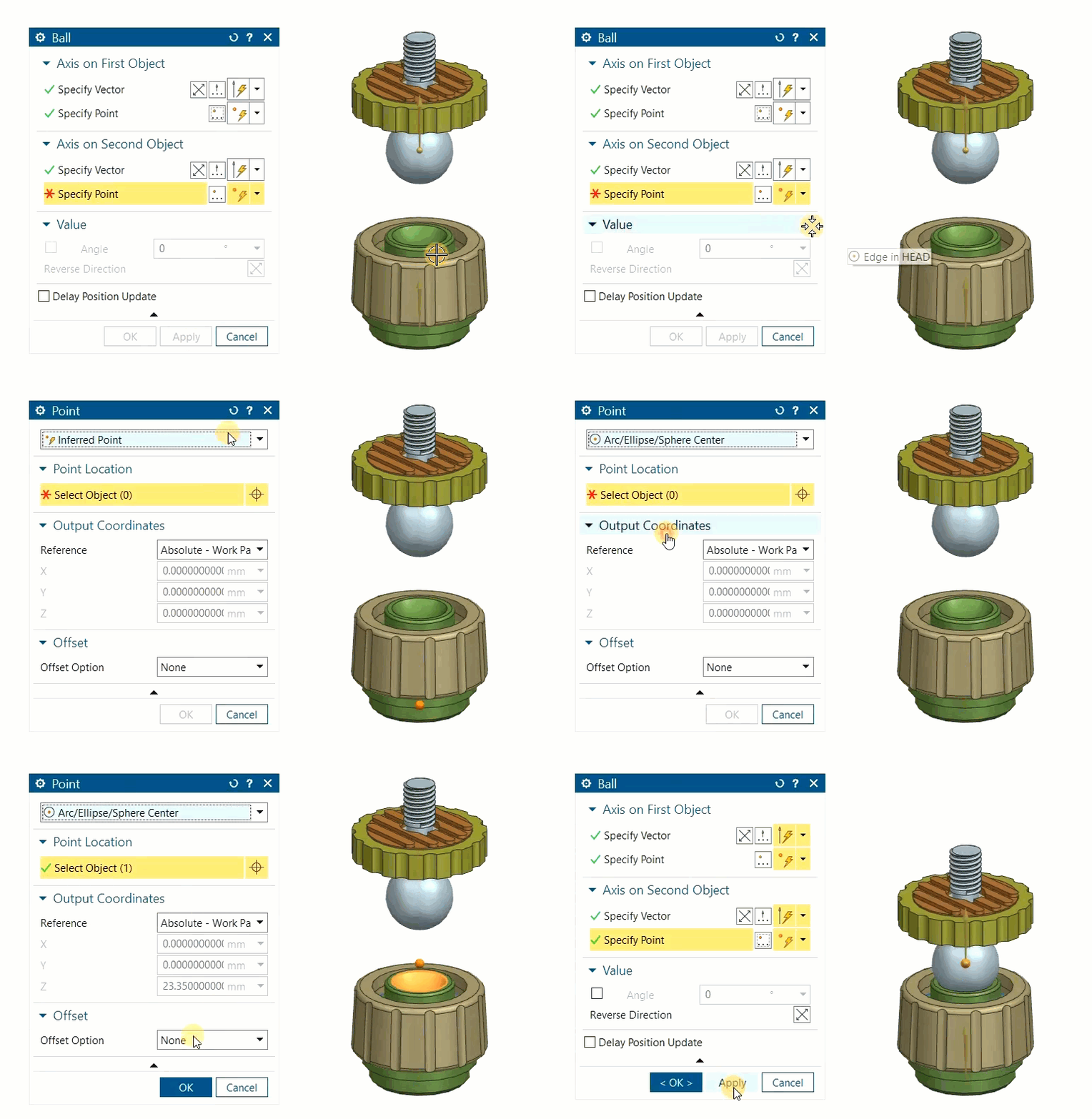
Step 8
Click OK to return to the Assembly Constraints dialog.
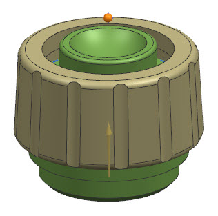
Step 9
Aligning the axes and points of the two components, Click OK to create Ball joint.
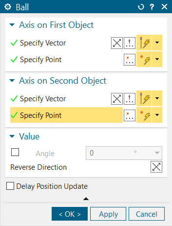
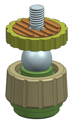
Step 10
Open the Assembly Navigator and observe that the Ball joint has been generated and can be found within the “Constraints” folder.
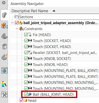
Step 11
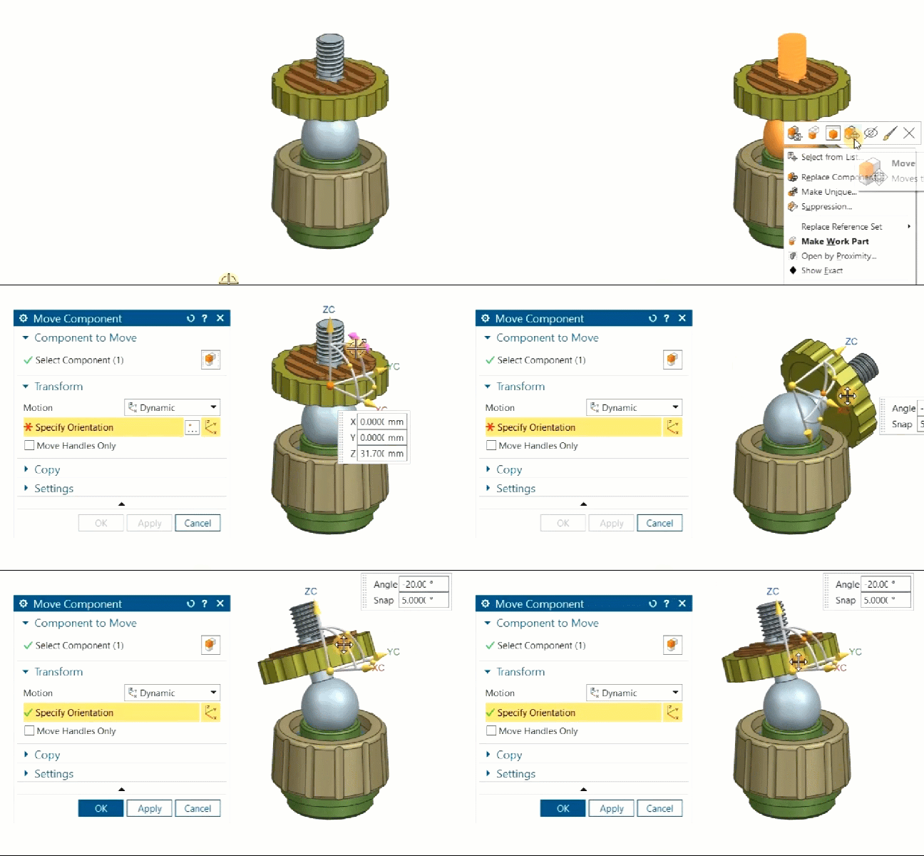
Using Move Component, You can notice here only three degrees of freedom that is rotate the constrained component about all three axes.
Check out our complete catalog of courses for engineering students and professionals. Stay tuned to i GET IT tech blog for more such tips.
If you like our Tech Blogs do share them using following share this post icon.
Megharaj
Related Posts
Lead-Acid vs. Lithium-Ion Batteries: Key Differences & Best Uses
Top AutoCAD 3D Commands & Shortcuts with Examples
What is Engineering Mechanics? – Introduction 101
How to Create Stitch Weld in Weldments using Autodesk Inventor?
How to Create Blend Curve on Surface using Siemens NX?
Find
Categories
Latest Posts
Top AutoCAD 3D Commands & Shortcuts with Examples
April 9, 2025What is Engineering Mechanics? – Introduction 101
March 10, 2025Popular Tags


