What is Single Line Diagram? – Meaning, Importance & Example
June 13, 2024 2024-11-11 13:29What is Single Line Diagram? – Meaning, Importance & Example
What is Single Line Diagram? – Meaning, Importance & Example
Single Line Diagrams (SLD) are essential tools in the field of electrical engineering, providing a simplified and clear overview of electrical power systems. By representing complex three-phase power systems with a single line, these diagrams offer a streamlined method for designing, analysing, and troubleshooting electrical circuits. This blog will delve into the intricacies of single line diagrams, their components, the steps to create them, and tools available for making effective SLDs.
Table of Contents
What is a Single Line Diagram?
A single line diagram, also known as a one-line diagram, is a simplified representation of an electrical power system. It uses single lines and standard symbols to denote the various components and connections in a power system. The primary purpose of an SLD is to provide an easy-to-understand schematic for electrical engineers and technicians, facilitating system design, maintenance, and troubleshooting.
Importance of Single Line Diagrams
Single line diagrams are crucial and used for several reasons. Below are the pointers highlighting the importance and use cases of Single Line Diagrams:
- Simplification: They simplify complex electrical systems by representing them with single lines and standard symbols.
- Design: SLDs are fundamental in the design phase, allowing engineers to plan and organize electrical systems efficiently.
- Analysis: They enable the analysis of power flow, fault conditions, and system stability.
- Maintenance: SLDs provide a clear reference for maintenance personnel, aiding in the identification of components and connections.
- Safety: By clearly depicting electrical pathways and components, SLDs help ensure the safety of personnel working on or near electrical systems.
Key Components of Single Line Diagrams
1. Power Sources:
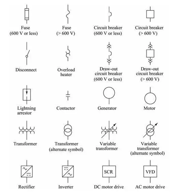
- Generators: Represent the origin of electrical power, depicted as a circle or a rectangle with a sine wave symbol.
- Transformers: Step up or step-down voltage levels, illustrated by two interlocking circles or coils.
2. Distribution Elements:
- Busbars: Thick horizontal or vertical lines that distribute power to different parts of the system.
- Circuit Breakers: Devices that interrupt the flow of electricity in case of faults, shown as a rectangle with a line through it.
- Disconnect Switches: Allow manual disconnection of circuits, represented by a simple switch symbol.
3. Protection Devices:
- Relays: Detect faults and initiate the operation of circuit breakers, often indicated by a box with the label “R”.
- Fuses: Protect circuits by breaking the connection if the current exceeds a safe level, depicted as a rectangle with a diagonal line.
4. Loads:
- Motors: Convert electrical energy into mechanical energy, shown as a circle with the letter “M” or a rectangle.
- Lighting Panels: Distribute power to lighting circuits, depicted as rectangles.

How to create a Single Line Diagram?
Step-by-Step Guide
- Identify the Components: Begin by listing all the components of the electrical system, including power sources, distribution elements, protection devices, and loads.
- Draw the Power Sources: Start by drawing the generators and transformers at the top or left side of the diagram.
- Add the Distribution Elements: Draw busbars and connect them to the power sources using straight lines. Place circuit breakers and disconnect switches appropriately.
- Include Protection Devices: Add relays and fuses to the diagram, ensuring they are connected to the relevant circuits and devices.
- Draw the Loads: Connect motors, lighting panels, and other loads to the busbars, representing them with their standard symbols.
- Label the Components: Clearly label all components and connections to enhance readability and understanding.
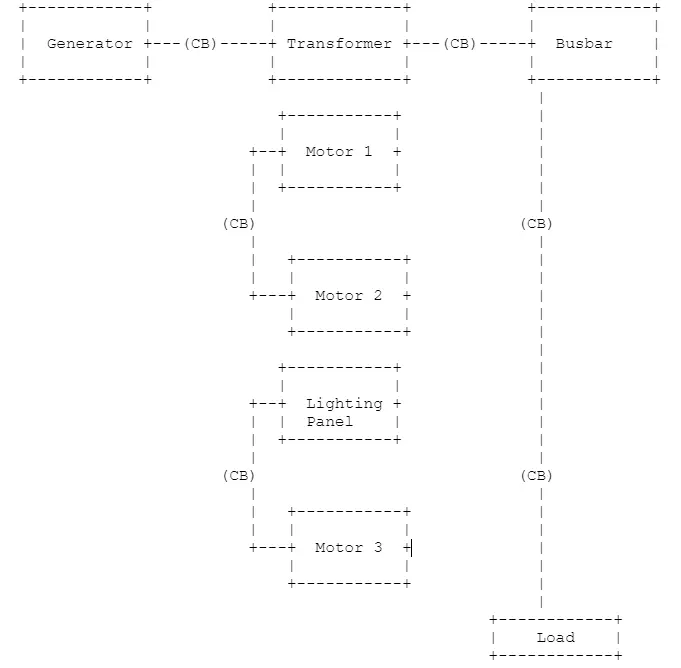
Example of a Basic Single Line Diagram

Tools for Creating Single Line Diagrams
- AutoCAD Electrical: AutoCAD Electrical is a specialized version of AutoCAD designed for electrical control designers. It provides comprehensive tools for creating SLDs, including symbol libraries and automated reporting.
- ETAP (Electrical Transient and Analysis Program): ETAP is a powerful software tool for electrical power system analysis and design. It includes features for creating detailed single line diagrams, performing load flow analysis, and simulating fault conditions.
- SmartDraw: SmartDraw offers a user-friendly interface for creating single line diagrams, along with a vast library of electrical symbols. It allows for easy customization and integration with other software tools.
- EPLAN Electric P8: EPLAN Electric P8 is a software solution for planning and designing electrical engineering projects. It provides advanced features for creating single line diagrams, generating bills of materials, and automating design processes.
- Visio: Microsoft Visio is a versatile diagramming tool that can be used to create single line diagrams. It offers a range of templates and shapes for electrical engineering projects.
Best Practices for Single Line Diagrams
- Standardization: Use standard symbols and conventions to ensure consistency and readability.
- Clarity: Keep the diagram uncluttered and straightforward, avoiding unnecessary details.
- Labeling: Clearly label all components, connections, and reference points.
- Documentation: Include supplementary documentation, such as legends and notes, to explain the diagram’s elements and functionality.
- Review: Regularly review and update the diagram to reflect any changes in the system.
Also read: Top 35 Electric Vehicle Engineer Interview Questions & Answers
Conclusion
Single line diagrams are invaluable tools in the electrical power industry, providing a clear and concise representation of complex power systems. They simplify design, analysis, and maintenance processes, ensuring safety and efficiency. By understanding the key components, steps to create an SLD, and utilizing the right tools, electrical engineers can effectively use single line diagrams to manage and optimize electrical power systems.
Incorporating best practices such as standardization, clarity, and regular updates will further enhance the utility of single line diagrams. Whether you are designing a new power system or maintaining an existing one, mastering the creation and interpretation of single line diagrams is essential for any electrical engineer.
Get EV Battery Certification by Tata Technologies
Understanding single line diagrams in electrical power systems and EV batteries might not be immediately apparent. However, both areas share a foundation in electrical engineering principles. A strong understanding of these principles is crucial for the safe and efficient operation of both traditional power systems and the complex battery packs that power electric vehicles. An EV battery certification course offered by i GET IT (Tata Technologies Education division), dives deeper into these electrical concepts while specifically focusing on EV Essentials, Battery Management System, Energy Storage and Battery Pack Design.
Explore our EV Certification Courses
Get a comprehensive understanding of EV technology!
EV CoursesContact UsMegharaj
Related Posts
What is Fluid Mechanics? – Introduction, Laws & Equations
What Is AutoCAD Software? Uses, Features & Practical Examples
Independent Front Wheel Suspension – Types, Benefits & Working
What is PLM? – Product Lifecycle Management [Detailed Guide]
Lead-Acid vs. Lithium-Ion Batteries: Key Differences & Best Uses
Find
Categories
Latest Posts
What is Fluid Mechanics? – Introduction, Laws & Equations
January 7, 2026What Is AutoCAD Software? Uses, Features & Practical Examples
December 18, 2025Independent Front Wheel Suspension – Types, Benefits & Working
November 10, 2025Popular Tags


