How to Use Synchronicity in NX 2312 Assemblies
February 28, 2024 2024-11-11 14:20How to Use Synchronicity in NX 2312 Assemblies
How to Use Synchronicity in NX 2312 Assemblies
Overview
In this TechTip, you will learn how to use Synchronicity in an assembly, in NX 2312.
Synchronicity in an assembly enables to configure the components and chosen facets in various modeling components in a single operation. This is time efficient, as it provides an aid for quick reconfiguring the components of an assembly while analyzing in case of design changes.
Prerequisites: Check whether the Early Access Feature is On in the Early Access Feature dialog box.
Please follow the below steps to use Synchronicity in an NX 2312 Assemblies
Step 1
Go to Files > Utilities > Early Access Feature > Assemblies command:

Step 2
Select Assemblies in the drop down Filter as shown in figure.

Step 3
Once Assemblies is selected the features will appear, in this we have to make changes in Enables shape with component positioning it’s State will be Off we have to right click on it and make it On.

Step 4
After making the changes restart the NX 2312, then the changes will get applied.
Harnessing Synchronicity by using Label as Modeling Component command
Step 1
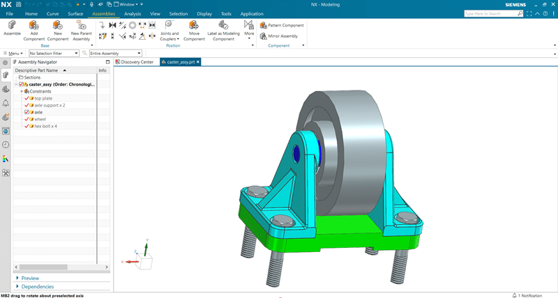
Open the caster_assy.prt in the modeling interface.
Step 2
Go to Assemblies > Position > Label as Modeling Component command.

Step 3
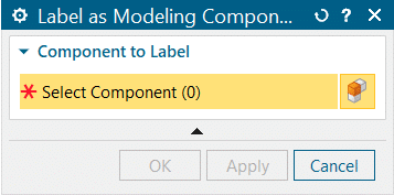
Lable as Modeling Component feature dialogue box will appear.
Step 4
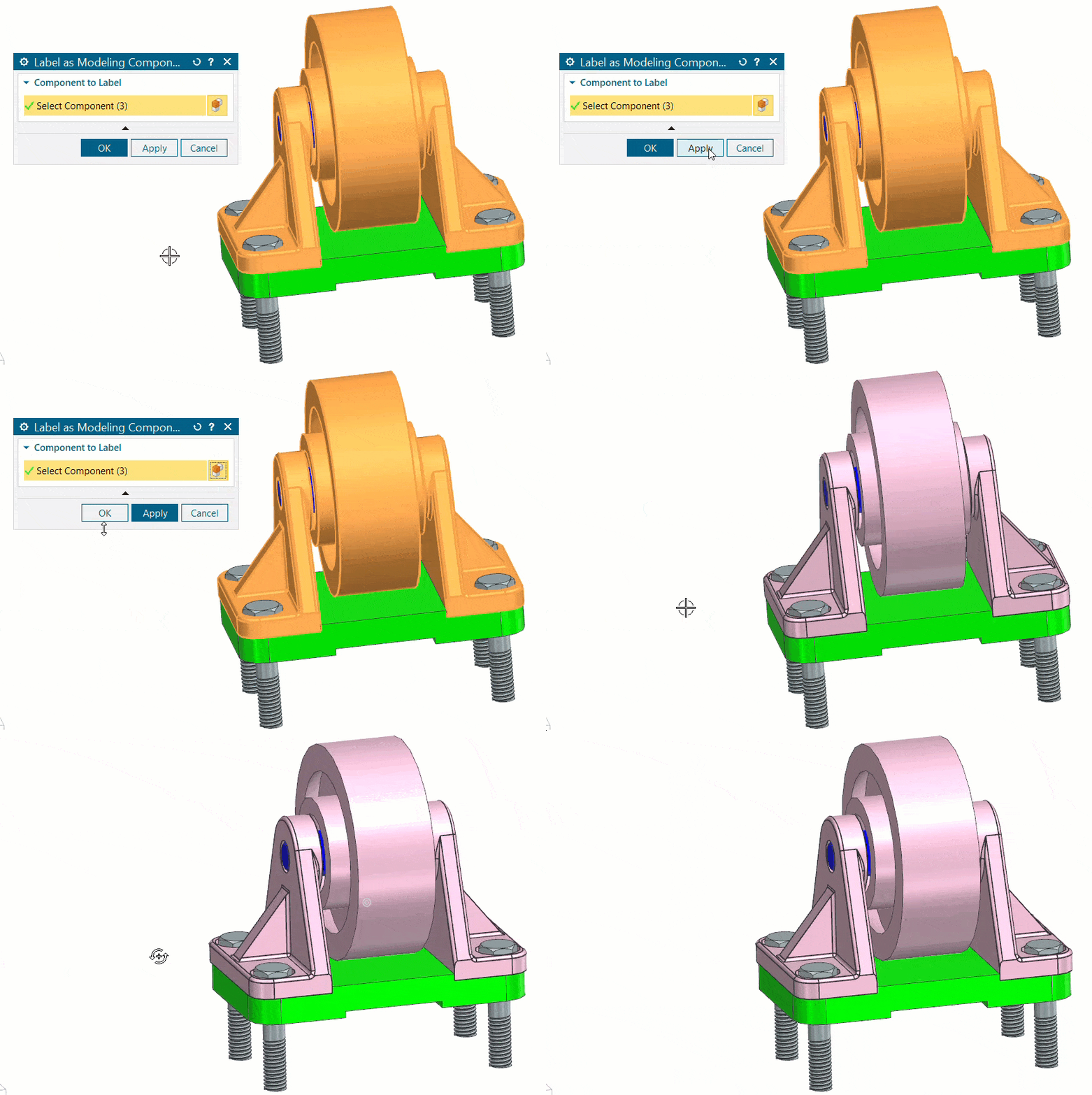
In the Select Component pane, select the components as shown:
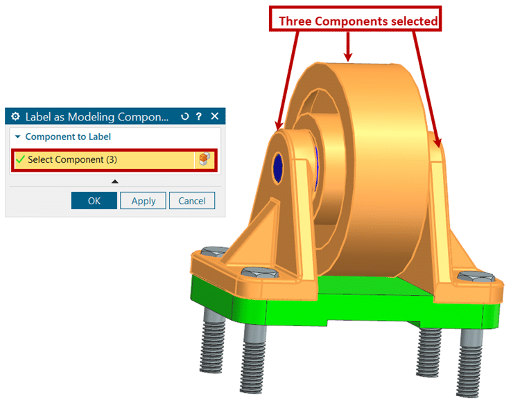
Click OK after selecting the component.
Step 5
Once you click OK in the dialogue box, the selected component’s color changes, as shown below. This indicates that the selected components are movable now.
Step 6
Now, if you observe the Position Section of Assemblies, Move Component command has been replaced by Move feature. This change takes place after selecting the components in Label as Modeling Component.

Step 7
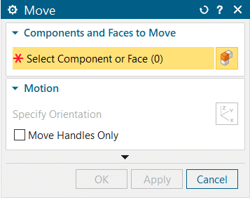
Once you select Move command, its feature dialogue box will appear as shown:
Step 8
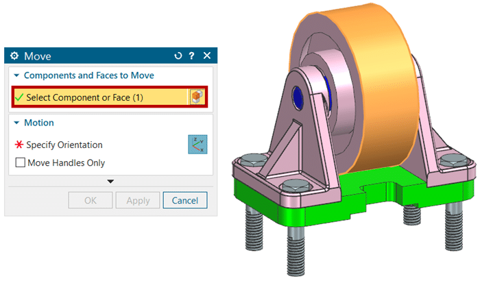
In Components and Faces to Move section, select the component which you want to move:
Step 9
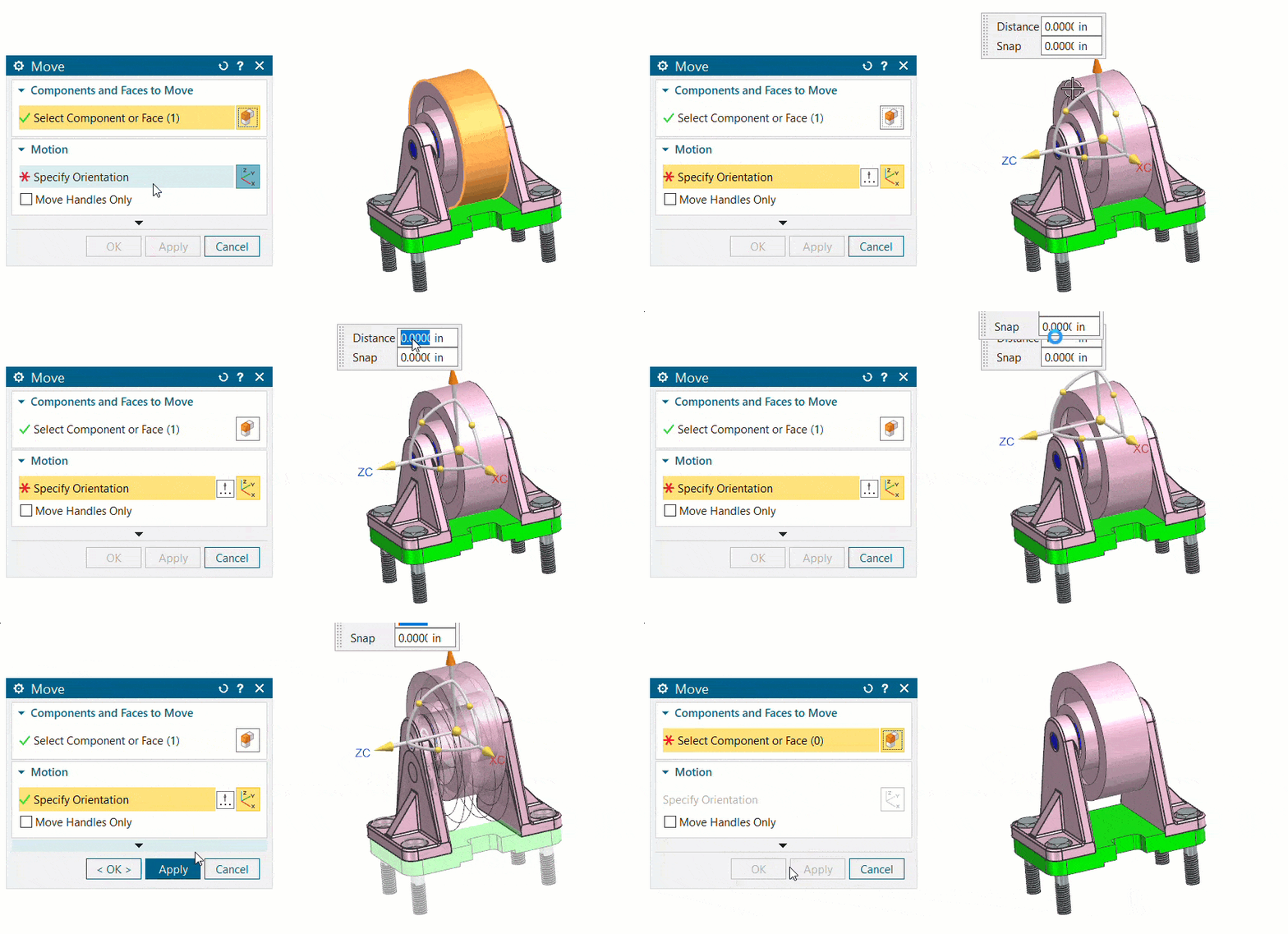
In Motion section, select the components direction in which it should move:
Step 10
Here you can see that the middle component has been lifted up by one Inch and both the side components have been adjusted their dimensions accordingly, as there are assembly constraints between them.
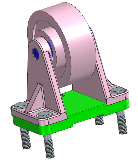
Step 11
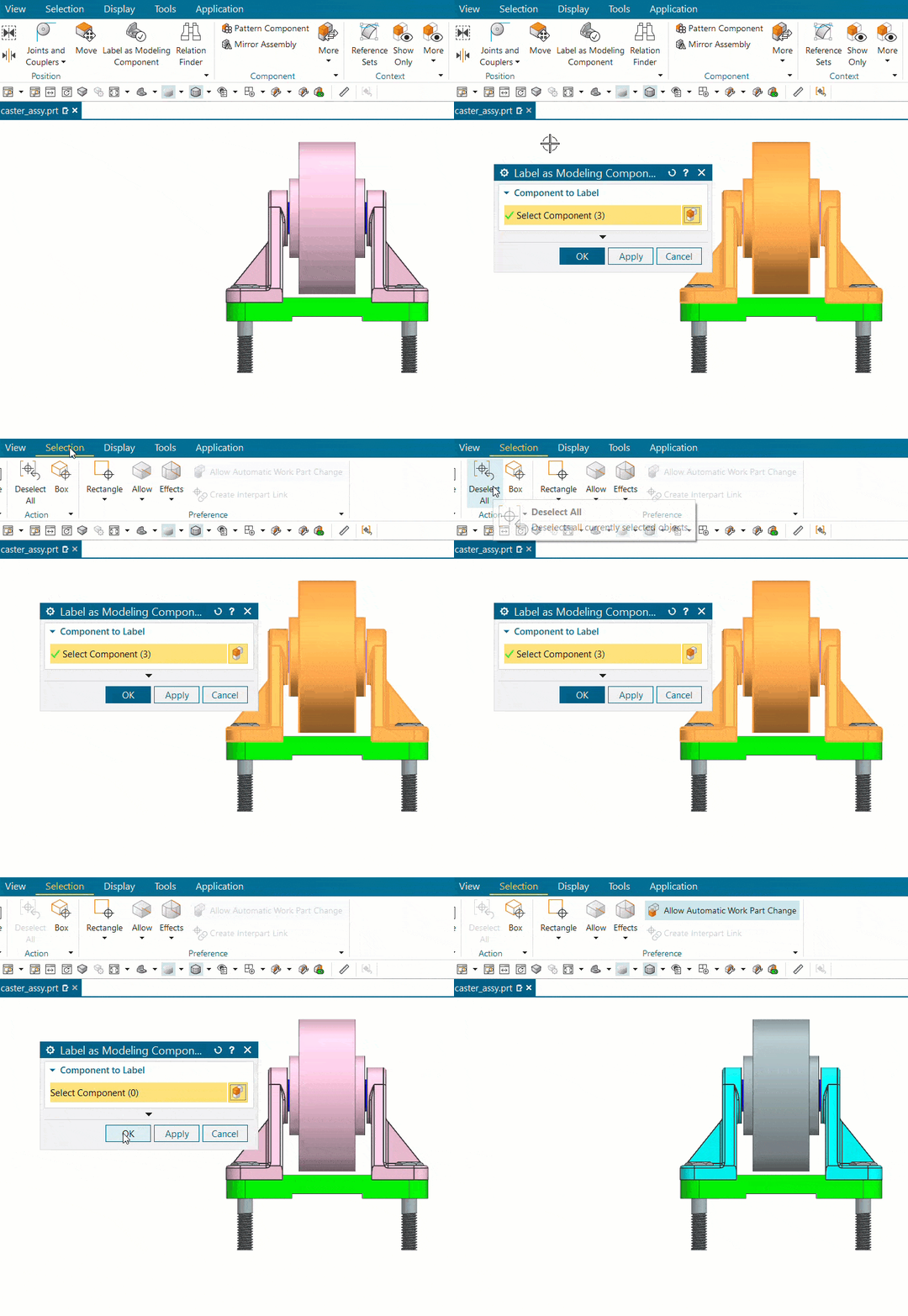
To deselect the labelled components from the Label as Modeling Component, select on the command, go to Selection tab then click on Deselect All option and click OK, as shown:
About i Get IT
i GET IT is our Tata Technologies eLearning solution designed to teach engineers how to be better in using today’s leading MCAD (Mechanical Computer Aided Design) applications and design skills.
For more tech tips and in-depth eLearning for Siemens NX, including this and new courses on other design solutions, please visit i GET IT. You can sign up and get FREE Subscription of our informative Newsletter.
Start your Upskilling Journey Now! Visit i GET IT Plans Page
If you have any questions, please reach out to iproducts@tatatechnologies.com or igetitsupport@tatatechnologies.com for help.
If you like our Tech Blogs do share them using following share this post icon.
Prateek Potnis
Related Posts
What is Fluid Mechanics? – Introduction, Laws & Equations
What Is AutoCAD Software? Uses, Features & Practical Examples
Independent Front Wheel Suspension – Types, Benefits & Working
What is PLM? – Product Lifecycle Management [Detailed Guide]
Lead-Acid vs. Lithium-Ion Batteries: Key Differences & Best Uses
Find
Categories
Latest Posts
What is Fluid Mechanics? – Introduction, Laws & Equations
January 7, 2026What Is AutoCAD Software? Uses, Features & Practical Examples
December 18, 2025Independent Front Wheel Suspension – Types, Benefits & Working
November 10, 2025Popular Tags


