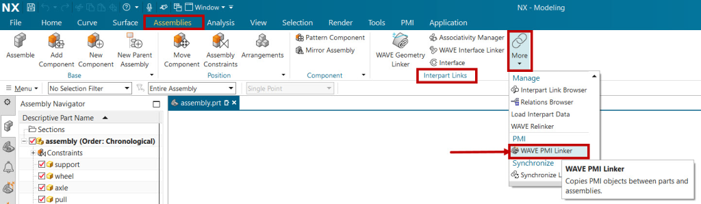
How to use Wave PMI Linker | Siemens NX 2206
December 2, 2022 2024-11-11 14:32How to use Wave PMI Linker | Siemens NX 2206


OR
Start your 3 days free trial now
Already have an account? Sign In
By clicking the button above, you accept our terms of use and privacy policy.
OR
(Ensure popup is allowed for this site)
Start your 3 days free trial now
Already have an account? Sign In
By clicking the button above, you accept our terms of use and privacy policy.

Submit details and we will get back to you!!!